Scanning Electron Microscopy for Root Cause Analysis
Scanning Electron Microscopy for Root Cause Analysis
A cracked component, corroded contact, or peeling coating shows where a failure happened, but not necessarily why. The visible damage could come from a material defect, unexpected loading, contamination, poor surface prep, or environmental exposure, or some combination of those. Scanning electron microscopy gets used a lot in failure investigations because it reveals microscopic surface features that visual inspection alone can’t catch, but it works best as part of a structured investigation alongside optical microscopy, EDX, FTIR, and cross-sectioning, not as a standalone test.
Why SEM Rarely Works Alone
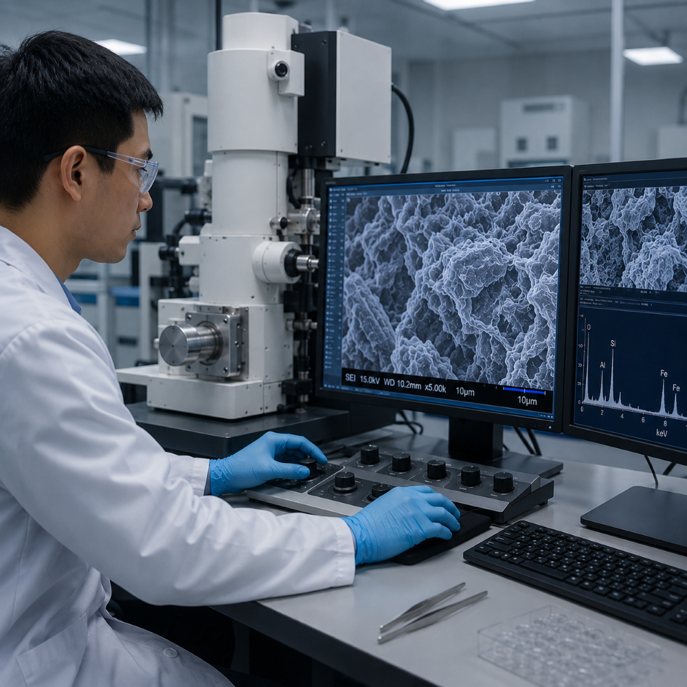
SEM produces high-resolution images of fracture surfaces, corrosion pits, particles, and coating defects, images that might reveal fatigue striations, brittle cleavage, ductile dimples, or the shape of a foreign contaminant. But the image by itself often isn’t enough to pin down the actual source of the problem. A particle might look metallic, but its composition still needs checking. A coating might have separated from a substrate, but the investigation still needs to establish whether that happened inside the coating or right at the interface.
| Technique | Information provided | Typical application |
| Optical microscopy | Overall failure location and surface condition | Initial examination and documentation |
| SEM | High-resolution surface and fracture morphology | Cracks, fatigue, corrosion, particle shape |
| EDX | Elements present at a selected point or area | Corrosion products and foreign particles |
| FTIR | Molecular identification of organic materials | Polymers, oils, adhesives, surface films |
| Cross-section analysis | Internal layers, interfaces, crack paths | Coatings, solder joints, delamination |
That’s why analysts usually pick several complementary techniques based on the material, the failure mode, and the actual engineering question being asked.
Start With Non-Destructive Examination
A solid failure investigation usually starts with visual inspection and low-magnification microscopy before the sample gets cut, cleaned, coated, or altered in any way. This preserves the original condition and lets the analyst document where the failure sits relative to the whole component. Optical and stereo microscopy can locate fracture origins, corrosion zones, and delamination boundaries, and SEM then gets applied to specific areas that need higher magnification rather than scanning the whole sample without a clear target.
Cleaning a fracture face before examination can strip away corrosion deposits or foreign material that turn out to matter later, and fitting broken surfaces back together can damage microscopic features too. Samples should get handled as evidence until the lab confirms the prep method.
Combine SEM With EDX for Particles and Corrosion
EDX works alongside SEM by detecting the characteristic X-rays a sample gives off, identifying elements within a selected particle, corrosion deposit, or fracture interface, and showing how they’re distributed across an area. SEM might show that a contaminating particle is angular and embedded in a contact surface, for instance, while EDX shows it contains iron, aluminum, or silicon, information that can then get compared against machining tools, surrounding materials, and production equipment.
In a corrosion investigation, elemental mapping might show chlorine concentrated near a pit or zinc spread around a galvanic corrosion zone. These results support the investigation, but they shouldn’t get treated as proof of the source without comparing them against service conditions and production history.
Bring In FTIR When Organic Material Is Involved
EDX identifies elements but usually can’t tell apart organic compounds with similar elemental makeup. A contaminating film containing carbon and oxygen could be an adhesive, a lubricant, polymer residue, or a degraded coating, and EDX alone won’t tell you which. FTIR provides a molecular fingerprint that gets compared against reference spectra to identify polymers, rubbers, adhesives, oils, and organic surface films.
Using both techniques together stops an investigation from settling for a vague description like “carbon-based contamination.” SEM shows where the film or particle sits, EDX gives the elemental picture, and FTIR pins down the organic material more specifically.
Cross-Sectioning Shows What’s Below the Surface
Some failures can’t be explained by looking at the outer surface alone. Coating delamination, solder-joint cracking, internal porosity, and subsurface corrosion often require the component to be embedded, cut, ground, and polished. A prepared cross-section can reveal coating thickness, layer uniformity, voids, crack paths, and whether separation happened within a material or between two different layers, with SEM and EDX then examining that exposed cross-section at higher resolution.
Because cross-sectioning is destructive, it should usually come after the initial documentation and surface analysis. Cutting too early, or through the wrong spot, can permanently remove the evidence needed to find where the failure actually started.
Give the Lab More Than Just the Failed Part
The quality of an investigation depends heavily on the background information that comes with the sample. A lab that only receives a broken component can produce detailed images and still not connect that evidence to a realistic failure mechanism. Before requesting scanning electron microscopy analysis, it helps to give ALS Testing the component’s function and material spec, where and how the failure showed up, production or field-service history, and any relevant heat treatment, coating, or assembly details.
ALS Testing also supports manufacturers with failure analysis projects in Malaysia, providing SEM-based investigations for automotive, electronics, and industrial components where detailed evidence is needed to support engineering decisions and quality improvement.
The highest-magnification image isn’t automatically the most useful result. A reliable root-cause investigation connects microscopic evidence with the component’s design, manufacturing process, and service environment, sequencing optical examination, SEM imaging, elemental analysis, and cross-sectioning correctly so the conclusion explains not just what happened, but why.
Related Post